This blog is currently a bit of a mess. I’ve given up–for now–on trying to keep a coherent order of episodes; eventually I will collect things and put them in the right place. But, for now, I hope that the story in this article is cute enough to stand on its own two legs.
A couple of weeks ago Robin Piedeleu left a comment in Episode 28, asking about orthogonal projections in graphical linear algebra; specifically, he asked
how would I go about forming the diagram for the orthogonal projection onto the kernel of a matrix?
This is a pretty standard exam type problem in ordinary linear algebra, and requires a fair bit of matrix hackery that one needs to memorise. I used to hate these kinds of problems, especially in exams, because I’d always make routine errors in calculations. Here, I think, the graphical notation really stands out both for pedagogical purposes and for calculation: I definitely make fewer mistakes!
This post will also be a bit quicker paced than usual because I want to get to the answer and actually perform some computations. I will omit many of the proofs, but will (quickly) explain what the concepts of orthogonality, orthogonal complements and orthogonal projections mean and how one deals with them diagrammatically.
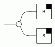
We start with a slightly different notation for arbitrary linear relations (I think due to Peter Selinger?) which is convenient for illustrating the two symmetries (colour swap and mirror image) of graphical linear algebra. Given a arbitrary diagram R: m → n, we will draw it as

The reason for this notation is that the symmetry breaking black square gives us a nice way to denote the mirror image diagram (R†: n → m).

(Filippo, in addition, likes to mirror the letter R; I’m a bit less keen on that but it does fit the spirit.)
We can also use this notation to show the colour swap symmetry

and combine the two to get the graphical notation for bizarro (combining colour swap and mirror image) of R.

Given the quick and dirty mood of this article, I will, from now on, leave out the labels on the wires; they can be reinserted back consistently and without too much effort; leaving them out makes the diagrams cleaner and faster to draw.
The linear relations of interest for this topic will be of the form R: m → 0, which we know are just a graphical linear algebra way of saying “a subspace of Qm“. We have a nice graphical way of denoting the sum and intersection of such subspaces. Given, R: m→0 and S: m→0, their sum R + S and intersection R ∩ S are, respectively:


The first question to tackle is what exactly does orthogonality mean, diagrammatically speaking?
Let’s start with the usual explanations. In the geometric interpretation of linear algebra, two vectors v, w are said to be orthogonal exactly when they are at right angles to each other. Algebraically, one defines the dot product of vectors:
v ⋅ w = v1⋅w1 + v2⋅w2 + … + vm⋅wm.
Then v and w are orthogonal exactly when v ⋅ w = 0. For example (1, 1) and (1, -1) are at right angles when we draw them in Q2 and indeed, 1⋅1 + 1⋅(-1) = 0.
Given a linear subspace R, one can define the orthogonal complement of R,
R⊥ = { v | ∀ w ∈ R. v⋅w = 0 },
which contains precisely those vectors that are orthogonal to everything in R.
The two standard facts to mention here are that R ∩ R⊥ = {0} (the only vector that is both in R and R⊥ is the zero vector) and R + R⊥ = V, where V is the entire vector space. It is for this reason that R⊥ is called a complement.
So how does this all work in graphical linear algebra?
It turns out that the answer is very easy. The orthogonal complement of R is simply its colour-inverted version. Indeed, one can show that (for any R: m→0)

which is the diagrammatic way of saying R ∩ R⊥ = 0. Since equations in graphical linear algebra are invariant under swapping of colours (and copying/adding is commutative), we get for free that

which is the diagrammatic way of saying R + R⊥ is everything.
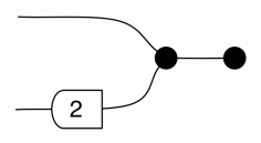
We might as well consider an example at this point. Consider the linear subspace of Q2 containing pairs (x,y) such that x + 2y = 0. The diagram for this is

The orthogonal complement is the colour swapped diagram, which is the following:

Note that the scalar has changed direction – this is of course a consequence of how the sugar for natural numbers is defined, since, recall:

Colour swapping the above makes the 2 gate point the other way.
Let’s just do a quick sanity check. An example of a vector that satisfies x + 2y = 0 is (6,-3). The diagrammatic spec of the orthogonal can be read as the subspace that contains vectors of the form (a, 2a) for any a. So let’s take, e.g. a = -1, obtaining (-1,-2). Now (6,-3)⋅(-1,-2) = -6 + 6 = 0. This is not a proof, of course, but I did say that I’m skipping those today.
Ok, so now what does it mean to project orthogonally onto some linear subspace R?
It means finding a linear transformation (or, if you prefer, a matrix) A such that
Ax = x if x ∈ R and Ax = 0 if x ∈ R⊥.
So, roughly speaking, we preserve everything in R and kill everything in its orthogonal complement. This is exactly how geometric projections work: for example if you want to project a 3D shape onto a plane. Much of the maths that underlies 3D graphics relies on this kind of linear algebra.
Now back to the story; let us construct the orthogonal projection diagrammatically.
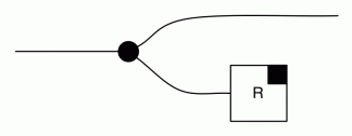
First, consider the following diagram.

We can think of this as the linear relation that represents the partial function that acts like the identity, but restricts its domain to R. It is thus not total, because, for example, it is undefined on the orthogonal complement.
The true orthogonal projection, given something not in R, should send it to zero. Here’s another partial function that does exactly that.

Now it turns out that to get the entire thing–the orthogonal projection onto R–we just need to sum up the two cases:

which gives us the diagrammatic specification for the orthogonal projection. Let’s take the right hand side above and rewrite it into the following, more aesthetically more pleasing diagram. This is graphical linear algebra after all, and we care about diagram prettiness.

We will use the above as the diagrammatic master formula for calculating orthogonal projections.
Let’s do a couple of worked examples, e.g. projecting onto
{ (x,y) | x + 2y = 0 },
i.e.

which was our example from before. Recall that the orthogonal complement here is:

Substituting into the master equation gives

To get the actual matrix we can do a little diagrammatic calculation.

where we used the Spider Theorem (Episode 23) twice in the third step to simplify the diagram. We could continue with diagrammatic calculation, but at this point it’s quicker just to multiply the constituent matrices (and remember, the order of multiplication is “backwards”):

You may feel like doing a sanity check to see if this indeed does the job. That is, take a vector in { (x,y) | x + 2y = 0 }, which the matrix ought to leave untouched, and take one from the orthogonal complement, which the matrix must send to 0.
Just for fun, let’s quickly do the calculations for other projection, onto the orthogonal subspace.

Here the matrix is, therefore,

But Robin’s original question was about projecting onto the kernel of some matrix. And here graphical algebra has some additional pretty insights. I mentioned in a previous episode that the bizarro of a matrix (combining colour swap and mirror) is the transpose. Thus, we have, for an m×n matrix A

That is, the colour swap of a matrix is the same thing as its transpose, mirrored.
This can be quite useful. In particular consider the kernel of A.

We know that if we want the orthogonal complement we need to swap colours.

But, using our new insight, this is the same as

So the orthogonal complement of the kernel of A is the image of its transpose. Simple.
Dually, the orthogonal complement of the image of A

is

which is the same thing as

So the orthogonal complement of the image of A is the kernel of its transpose. These trivial consequences of graphical linear algebra notation are sometimes called the Fundamental Theorem of Linear Algebra.
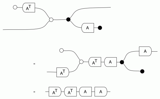
Now we can, given A, calculate a formula for the orthogonal projection onto its image. Substituting the relevant bits into the master formula gives:

From which we can read off the somewhat mysterious formula A (ATA)-1 AT that appears in many linear algebra textbooks.
For the projection onto the kernel of A we get

which doesn’t obviously simplify into a “textbook formula”, but is just as easy to use in calculations.
So, since we’ve done loads of random calculations so far, let’s do one more for the road. Let’s say we want to calculate the orthogonal projection onto the kernel of

which, as a matrix is, diagrammatically

The kernel is thus

and the orthogonal complement of the kernel is

It remains to plug all the bits into the master formula for calculating projections and simplify:

which multiplies out to give

Last week I had the pleasure of visiting the Perimeter Institute for Theoretical Physics. I gave a talk about graphical linear algebra, which was recorded and available to watch online here. I emphasised the “computer science” way of looking at string diagrams as a resource sensitive syntax. That story will eventually make its way onto the blog in full, for now you can only read the beginning.
One interesting thing about the Perimeter Institute is the front entrance.

The Greek inscription translates to
Let no one uninterested in geometry enter here.
The phrase is a tribute to the phrase that was said to adorn the entrance to Plato’s Academy:
Let no one unversed in geometry enter here
I like the small change: the Perimeter Institute, in its mission statement, emphasises pedagogy as well as research.
The Perimeter Institute is the perfect research institute. It is a research factory with the best minds in theoretical physics. Crucially and refreshingly, it was built with researchers in mind. For example: there are blackboards everywhere, the open spaces encourage interactions, the architecture is inspiring and the food in the cafeteria is amazing. The contrast with 21st century British academia was… a bit depressing, and I was sad to leave.
If somebody wants to part with a few hundred million dollars, I’d love to set one up for theoretical computer science and category theory. Get in touch, philanthropic billionaires!

It was good to see you at the Perimeter Institute last week! Nice to see my quick comment over lunch (or was it during one of the tea breaks?) playing a role here. A small correction: in the definition of orthogonal complement, it should be .
.
LikeLike
Thanks, I fixed the typo!
It was great to catch up. And what comment are you talking about? I must have forgotten and internalised it, otherwise I would’ve credited you!
LikeLike
It was basically just a reminder of what you already knew: that bizarro is transpose and mirroring is inverse, and thus colour swaps are simply inverse transposes.
LikeLiked by 1 person
I was jet lagged last night and couldn’t sleep — then I constructed the diagram for the orthogonal projection in my mind and had to get up to spend the next few hours doing computations 🙂 I got really excited… this is one of my favourite parts of the story so far.
LikeLike
Just noticed another typo—Perimeter Institute for Theoretical Physics seems to have encountered a copy morphism. Wishful thinking? 😉
LikeLike
Haha, thanks!
LikeLike
Thanks a lot, Pawel! I ended up working out the solution for the projection onto the kernel for myself and it was a great exercise in trying to connect the usual notion of linear algebra with the graphical formulation. I really like the two-colour notation for the bizarro and the derivation of the usual textbook formula for the projection onto the image. All cool applications of the graphical notation!
LikeLike
Thanks! There’s a whole bunch of stuff that becomes obvious with the notation, e.g. that projections are symmetric (preserved by transpose/bizarro).
LikeLike
Enjoyed your video at the Perimeter Institute. Wish the video was at YouTube, because then it would have been recorded in my “History” at YouTube, making it easier for me to find it at some future date.
Also, are the viewgraphs from your PI talk available somewhere? Excellent work/pedagogy there! Thanks, Keith
LikeLike
Thanks! It actually is available on YouTube, on the official PI page.
Here’s a direct link: https://www.youtube.com/watch?v=Q0BNCGW9vFA
LikeLike
Could I also ask a probably dumb question?
Is there any way of getting from your main web page, https://graphicallinearalgebra.net/
ti https://graphicallinearalgebra.net/episodes/ (which I only found by doing a Google search on something)?
If there is, I couldn’t find it!
LikeLike
I’m not entirely happy with this WordPress theme either, not everything is entirely straightforward. I’m going to work on a book version (and update the blog) this summer, so hopefully you will see some improvements soon.
LikeLike
I’m very curious about the proof that inverting the colours of a subspace gives us its orthogonal complement.
Has it ever been shown in any of the papers linked in this blog? I skimmed some of them, and I haven’t found any that mentions orthogonality.
LikeLiked by 1 person
As far as I know, the proof is not published anywhere. I thought I had it at the time I was writing it up, but someone (Joao Paixao) challenged me afterwards and I couldn’t reproduce it… I would like to sit down and try to write it down properly at some point. So afaik it’s open.
LikeLiked by 1 person
I’d also like to have a go at it 😊
LikeLiked by 1 person
I found a simple proof, but I haven’t found the time to write it down properly yet.
(The main idea is composing the kernel of A^T with (Av)^T, showing the result of the composition is equal to the zero subspace, which means the dot product of any member of the kernel with any vector of the form Av is zero)
However, it is not purely diagrammatic since I don’t see a way to express the dot product of two vectors in diagrammatic language. Obviously the dot product is not a linear map but rather a billinear map, which means can’t be expressed as a diagram. So my proof ends up being very similar to the traditional approach.
I’ve considered defining a new generator that does multiplication, however I’m not sure what all the axioms are, and what new PROP will arise from these new generators and axioms.
LikeLiked by 1 person
Maybe I’m missing something here because I haven’t looked carefully at the issue in question here yet, but if you can represent your vectors as matrices, you should be able to do dot product diagrammatically because:
1) We can multiply matrices, diagrammatically,
2) The dot product of two n-dimensional vectors is the same as multiplying the corresponding nx1 and 1xn matrices together, and
3) Transposing a matrix, diagrammatically, is just the bizarro diagram.
LikeLiked by 1 person
Sorry, I was a bit unclear in my previous comment.
Yes, the dot product can be expressed that way diagramatically. Multiplying a vector with the transpose of a vector is the dot product, and using that I’m able to come up with a simple proof.
However, said proof is not done purely diagramatically, because I needed to view one of the subspaces in the lens of “traditional” linear algebra, to be able to construct the transposed vector in the diagram.
What we can’t do is have a diagram that takes two vectors as an “input”, and “outputs” their dot product.
So I don’t think I can find a purely diagrammatic argument that says two subspaces are orthogonal complements. Because there isn’t even a purely diagramatic way to say two “inputs” are orthogonal (yet).
LikeLike